Configuration of logger
Logger Configuration is used to change the properties of
the logger and start a new session of logging.
Buttons
- OK:
Click to save the changes to logger and close the
dialog.
- Apply:
Click to save the changes to logger.
- Cancel:
Click to close the dialog without
saving the changes.
- Help:
Open help file for Configuration of
Logger.
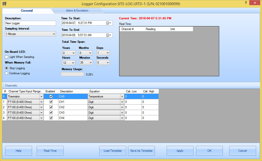
General
General section contains general properties of the logger.
- Description:
Specify the description of the logger.
Up to 30 characters.
- Sample
Interval:
This field
specifies the time span the logger will wait between two measurements
sampling. Valid settings are:
|
Sampling Interval for Fast Sampling
Mode |
Sampling Interval for Normal
Sampling Mode |
|
20, 30,
90 milliseconds * |
5
seconds to 9 seconds in 1-second increment |
|
100,
200
900 milliseconds * |
|
|
1,2,3,4
seconds * |
1 minute
to 59 minutes with 1-minute increment |
|
|
1 hour
to 12 hour with 1-hour increment |
For LRHT-1/2,
PRECISE-LOG logger, the minimum sampling interval is one second.
For SITE-LOG logger, if the sampling interval
you set is 4 seconds or faster, the logger must be powered by an external
power supply during the logging period of time.
For iLog logger, you can
specify the fast sampling mode's value (either one second or five
seconds)
Making changes
to the Sampling Interval will affect Total Time Span
fields.
On-board
LED:
Check this field to enable the on-board
status LED. If the LED is enabled it will flash each time when it samples data
to indicate:
1.
The logging is active if the LED is in
green.
2.
The logger is in alarm state if the LED
is in red.
3.
The battery will die soon if the LED is
in amber.
If you do not need LED indication,
please uncheck this field to increase the battery
life.
When Memory
Full:
If you want the logger to stop logging when
the memory is full select Stop
logging. If you want the logger to continue logging and overwrite the
oldest data with new data (FIFO), you choose Continue logging.
Time to Start & Time
to End:
These two fields specify the desired time
the logger will start logging data and the time to stop logging
data.
Making changes to the Time to End will
affect Total Time Span fields mentioned later.
If you have selected the Continue logging field, when the memory
is full, both start time and end time will move forward
accordingly.
Total Time
Span:
These fields are an alternate way to
specify the total logging time from the start time you specified
above.
Changing on these fields will affect the
Time to End field.
Memory
Usage:
Specify the memory usage for the new setting.
If you
change Time to Start and Time to End, Total Time Span will change
accordingly.
Alarm & Excitation (for SITE-LOG and iLOG series)
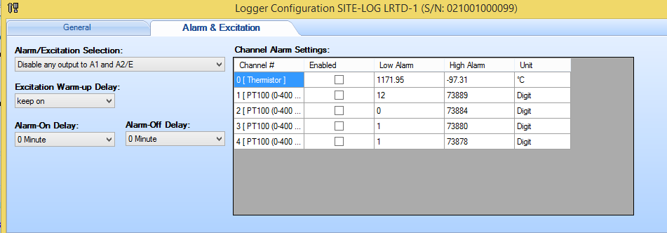
- Alarm/Excitation
Selection:
Specify how the alarm and excitation will output
to C/A1 and C/A2 strips.
Available selections:
Disable any output -> C/A1 and C/A2:
Both C/A1
and C/A2 are disabled.
High alarm -> C/A2 only:
C/A1
is disabled. C/A2 is controlled by high alarm only. i.e. if high alarm is
tripped turn on C/A2.
Low alarm -> C/A1 only:
C/A2
is disabled. C/A1 is controlled by low alarm only. i.e. if low alarm is
tripped turn on C/A1.
High alarm -> C/A2 and low alarm ->
C/A1:
C/A1 is controlled by low alarm and C/A2 is controlled by
high alarm.
High alarm and low alarm -> C/A1:
C/A2
is disabled.
C/A1 is controlled by both low and high
alarm.
Excitation control -> C/A2:
C/A1 is
disabled.
C/A2 is controlled by Excitation control
only.
Excitation control -> C/A2 and both alarms ->
C/A1:
C/A1 is controlled by both low and high alarms.
C/A2 is
controlled by Excitation control.
Excitation control -> C/A2 and
low alarm -> C/A1:
C/A1 is controlled by low alarm.
C/A2 is
controlled by Excitation control.
Excitation control -> C/A2 and
high alarm -> C/A1:
C/A1 is controlled by high alarm.
C/A2
is controlled by Excitation control.
- Alarm-On
Delay:
This filed specifies a time delay before
applying alarms.
If delay certain time before
sending out alarm notification if there is an alarm.
Valid range:
0 minute to 59 minutes.
- Alarm-Off Delay:
This filed
specifies a time delay from the alarm is off the threshold to the alarm is
cleared.
Valid range: 0 minute to 59
minutes.
- Excitation Warmup
Delay:
Specify the warm-up delay between the time the
excitation control is turned on and the time the logger starts to sample
the current reading.
Available selections: 10 to 240 seconds in 10 seconds
interval.
- Channel Alarm
Setting:
Channel#:
Specify the channel
number.
Alarm Enabled:
Specify if current channel will
enable or disable alarm function.
Low Alarm:
Specify the
low alarm threshold in physical unit.
High Alarm:
Specify
the high alarm threshold in physical unit.
Unit:
Specify the unit
for the alarm thresholds.
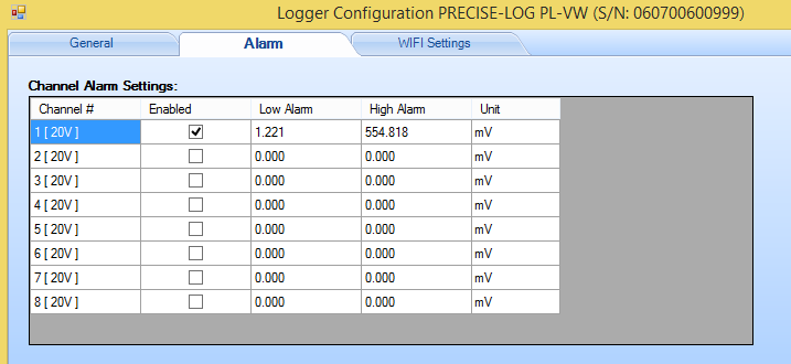
Alarm for PRECISE-LOG series:
Refer to the same fields in above section for details.
Wifi Settings for PRECISE-LOG with WIFI Module:
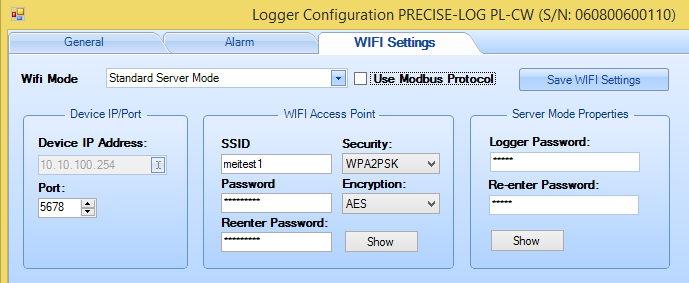
- Wifi Mode:
Standard Server Mode:
Both data logger and the host PC join an existing WIFI network. Then the host
PC can create USB Server connection to communicate with the data
logger.
AccessPoint Server Mode: The data logger will create a WIFI access
point and wait for the host PC to join. After joined, the host PC can use IP
address: 10.10.100.254 to communicate with the data logger.
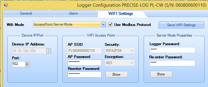
- Device IP/Port:
Device IP Address is read only and it is assigned by
the WIFI network router. In AccessPoint server mode, it is fixed to
10.10.00.254.
- Port:
The port number the logger will use.
- Wifi Access Point:
This section is used to set the settings for the
Wifi network the logger will connect to. Or the AP the data logger will create
if the Wifi Mode is set to AccessPoint Server mode.
- Server Mode Properties:
This section specifies the password at the
logger side. SiteView must use this password to communicate with the
logger.
Channels:
- Channel#:
Specify the channel number.
- Enabled:
Specify if the channel is enabled or
disabled. Logger does not record data for those disabled channels.
- Description:
Specify the description of the
channel.
- Equation:
Specify the equation of the channel.
- Cali. Low & Cali. High:
Specify the Zero
calibration value in raw dight value.
© 2018 Microedge Instruments Inc.